INSPECTION OF STEAM TRAPS

The aim of purge station inspection is to detect any anomaly, be it functional, efficiency or any other kind. Among the most frequent incidents detected during the inspection of purge stations are internal or external steam leaks, inappropriate design or sizing, defective assembly, inadequate discharge temperatures, obstructions, blockages, thermal water hammers and excessive backpressure.

Statistically more than 80% of the detected incidents are related to steam leaks and energy efficiency, and the rest with operational incidents. Frequently, more than 20% of purge stations present steam leaks or low energy efficiency, a situation incompatible with rational use of energy and sustainable growth. The establishment of an effective program of inspection and predictive, preventive and corrective maintenance considerably reduces all the mentioned incidents and is especially useful to reduce steam leaks, optimize energy efficiency and reduce the emission of greenhouse gases in steam networks. The table shows indicative values ​​of incidents in purge stations in correspondence with the frequency of inspection and maintenance.


Inspection frequency

Failure rate (%)

24 months 30
18 months
25
12 months
15
  6 months
7
  3 months
5
  1 month
3
 Monitored
<0,2


METHODS OF STEAM TRAPS INSPECTION

Verification of purge stations must check not only the status of all their elements (steam trap, blocking valves, bypass ...), but also their suitability and size for each application, and their energy efficiency. This verification usually requires some experience and the combination of several inspection methods, which are described below:

DIRECT VISUAL INSPECTION

Observing the atmospheric discharge of a purge element requires some experience to distinguish between live steam and expansion steam. The presence of flash steam in the discharge of steam traps is natural and does not imply existence of live steam leakage. However, the formation of flash steam is greatly reduced in tracing applications due to the partial use of the sensible heat of the condensate, a recommended practice to increase energy efficiency that is an inalienable objective at present.

Ocular observation of atmospheric discharge of a steam traps allows its diagnosis, although it is difficult to differentiate live steam from flash steam, which can lead to errors. The following figures explain possible situations:

Steam trap flooded
Steam trap right
Steam trap leaking
Steam trap blowing

The first figure shows a condensate jet without flash steam indicating that the trap is small and cannot evacuate the whole condensate charge. The second figure shows a condensate jet mixed with flash steam (slightly opaque vapor cloud), indicating steam trap discharging correctly. The third figure shows a small leak of live steam (small transparent steam plume). The fourth figure shows a large vapor leak.

When the steam trap does not discharge to the atmosphere but into return collector, then to be able to make visual inspection it is necessary to have a test valve. This can be installed before or after the steam trap. If it is placed behind the trap, there should be a shut-off valve behind the test valve to isolate the steam trap from the condensate return collector.

The test valve installed in front of the trap, has the advantage of allowing verifying if what reaches it is live or condensed steam. Indeed, when opening this valve very lightly, if the trap is working correctly, it should leave a few drops of water and immediately steam; on the other hand, if only dry steam comes out, it is a sign that the steam trap leaks live steam, since flash steam cannot exist in front of it. Note that if the test valve is mounted behind the trap, it is natural to discharge flash steam, even if the trap is functioning correctly, and this makes the correct diagnosis difficult.

In case of intermittent steam traps (thermodynamic and inverted buckets), the test valve after the steam trap allows verifying if its operation is intermittent; in another case the steam trap leaks live steam. If the operation is intermittent it is very difficult to distinguish if there is live steam in the discharge or expansion steam, so the diagnosis is not very reliable. This is due to the fact that, when the test valve is opened, the actual working conditions of the steam trap are modified, eliminating the back pressure.

In case of continuous discharge steam traps (buoy), the post-trap test valve always discharges flash steam, mixed or not with live steam; therefore, the visual diagnosis may be inaccurate. In fact, it is common and well known that steam traps that do not work well when they discharge to a condensate return collector, nevertheless function correctly when their discharge is diverted to the atmosphere.

VISUAL INSPECTION BY PEEPHOLE:

Inspection of stea traps through peepholes replaces test valves with glass peephole placed in the pipe in front of or behind steam traps. There are 3 types of peepholes:

   ♦Simple
   ♦ Siphoned
   ♦ Electronics:

Simple sight glass is usually installed behind the purge element and only allows verifying the existence of flow through it but it is generally not possible to differentiate if it is live steam or expansion steam. Siphoned peephole incorporates an internal siphon. It must be installed in front of steam traps and, therefore, allows differentiating the state of the fluid (condensate or live steam) because being installed in this position, if steam passage is observed it can never be flash steam. On syphoned glasses three different situations can be observed as shown in the following figure:

   1.- Fully waterlogged aspect: It means steam trap flooded due to lack of discharge capacity, obstruction or blockage.

   2.- Liquid level right up to the edge of the central part of the siphon: It means steam trap working properly without t loss of steam.

   3.- Liquid level lower than the edge of the central part of the siphon: It means steam trap leaking live steam

Inspection by siphoned peephole

The utility of peepholes is limited to low pressures and has the disadvantage of rapid fouling and loss of transparency due to the progressive deposition of oxide particles in their glasses, canceling their usefulness and increasing maintenance costs.

A more sophisticated type of peephole is the electronic type, which consists of a small container with an internal electrode. When condensate is present the electrode closes the electrical circuit by conductivity. The electric circuit is open when there is steam leakage. The signal is collected by an external measuring device connectable to the container, but its use is practically null due to high cost and poor reliability, because the electrode is short-circuited when coated with a film of iron oxide (magnetite) that cancels its function of diagnosis.

INSPECTION BY MEASUREMENT OF TIME:

This method is only applicable to steam traps with cyclic operation and it measures the time that elapses between two consecutive discharges of the steam trap. A stopwatch is not necessary, but just mentally count 101, 102, 103, ... to establish with sufficient validity the duration of the steam trap cycle in seconds. If the trap works continuosly without any cycle, three situations can occur:

   1.- Steam trap is cold: It means the trap is our of service or blocked.

   2.- Steam trap is warm: The trap is flooded (stack, undersized, high backpressure, ...).

   3.- Steam trap is very hot: It means the trap is blowing steam.

If the trap opens cyclically it must be verified that the duration of its cycle is not excessively short. In thermodynamic disc steam traps, the cycle time should not be less than 30 sec; otherwise, the shorter the cycle, the more deteriorated its internal valve will be and the greater energy loss will be.

INSPECTION BY MEASUREMENT OF TEMPERATURE:

This method, if it is not joined to another, usually leads to errors since it requires knowing more information than is usually available in the field, namely:

   ♦ Steam trap type (continuous or intermittent discharge); discharge temperature (subcooled or at boiling point).

   ♦ Application (drip well, process, normal tracing, critical tracing, turbine, tank heating, ...).

   ♦ Inlet pressure (may vary due to regulating valves, charge variations, ...).

   ♦ Outlet pressure. This is always an unknown quantity. (It is not enough to know the pressure in the general retourn collector, but the one that exists just at the outlet of the steam trap, where there may be strong variations due to the formation of local flash steam at this point. This value significantly affects the correct operation of the trap, causing serious problems).

In small-flow traps, temperature measurement should generally be ruled out since ultrasonic detection is sufficiently reliable.

INSPECTION BY ULTRASOUND

It is a fast and quite reliable method to detect internal steam leaks. It consists of capturing the ultrasound generated by passage of steam or gas through an orifice. In effect, the flow of gas or steam at high speed through a narrowing generates noise in a wide range of frequencies, highlighting the harmonic that corresponds to a narrow area of frequencies around 39 KHz (+/- 2 KHz).

To apply the ultrasound method it is advisable to know how steam traps work, their type of discharge (continuous or cyclic), and select the sensitivity of the ultrasound instrument corresponding to the steam pressure; then apply the contact probe firmly on the steam trap to read the diagnosis on its LCD screen.

Gas & Steam leak detector

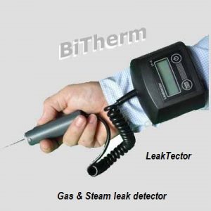
The figure shows the BiTherm ultrasound detector, model "LeakTector LT3-EX". This device is equipped with contact probe, optional directional probe for leak detection of compressed gas from a distance, discontinuous sensitivity selector and rechargeable battery. Its intrinsic safety certificate "EX II 1G Ex ia IIC T4 Ga" makes it suitable for use in potentially explosive atmospheres and its high sensitivity allows to diagnose very small steam leaks.

The reliability of this method depends on the mode of adjustment of the measurement scale and the user experience. To avoid diagnostic errors and simplify their use, it is recommended to use detectors with a continuous scale selector, since sensitivity adjustment is critical and depends on the skill of the operator and the results are not always reliable.

Note that the ultrasound method loses reliability when the local back pressure behind the purge element is very high and the differential pressure is reduced to values below 1 bar (see document limitations of ultrasound ...).

Warn that in case of doubt, for example in the high flowrate steam traps where a large amount of flash steam is produced that can generate ultrasound and be interpreted as a live steam leak, several ultrasound readings must be made, one on the steam trap and other 1 or 2 measurements downstream of it. Comparing both measurements, if the level of ultrasound detected is similar at all points, the existence of steam leakage is likely; on the contrary, if the ultrasound is attenuated downstream, it would be due to flash steam, not by passage of live steam.

INSPECTION BY REMOTE MONITORING (SmartWatchWeb™)

This is the most reliable method since unlike the rest, where only the situation is assessed at a given time, the monitoring takes into account the evolution of the parameters that define the operation of the trap over time, identifying substantial changes that they are clear indicators of failures or anomalies.

The monitoring can be total or partial depending on the parameters monitored: ultrasound, temperature, and back pressure. For more information go to Monitoring.